
Digital Electronics
Digital Electronics: Overview
This topic covers concepts such as Types of Signals, Analogue Signals, Digital Signals, Logic Gates, Truth Table in Logic Gates, The NOT Gate, The OR Gate, The AND Gate, The NAND Gate, The NOR Gate, Basic Gate or Fundamental Gate, etc.
Important Questions on Digital Electronics
The same input signal is applied to both the (input) terminals of a given logic gate.
If the output is the(i) same as the (common) input signal
(ii) inverted with respect to the (common) input signal,
Identify the logic gate/s involved in each case.
Write down the output at for the inputs and
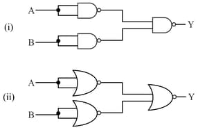
Identify the logic gates marked and in the given logic circuit.
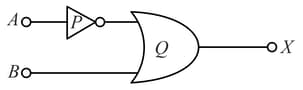
Identify the logic gates marked P and Q in the given logic circuit.
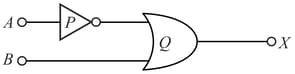
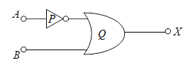
(i) Identify the logic gates marked P and Q in the given logic circuit.
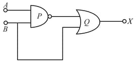
The inputs A and B are inverted by using two NOT gates and their outputs are fed to the NOR gate as shown below.
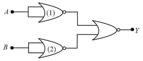
Analyse the action of the gates (1) and (2) and identify the logic gate of the complete circuit so obtained.
What is the difference between analog and digital signal?
Show that this electrical circuit is analogous to Gate.
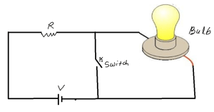
Discuss the operation of not gate by using electrical switches, bulb, resistor and battery.
What are analog and digital signals?
Minimum numbers of gates that are required for gate is four.
How many gates are required for gate?
How many minimum gates are required to obtain gate:
How many minimum gates are required to obtain gate:
The XNOR logic gates are used in _____ detecting circuits which are to detect Odd parity or even parity bits in digital data transmission circuits.
The expression of XNOR operation between variables A and B is represented as A ⊙ B. Now again, the truth table is satisfied by the equation AB + ĀB ̅. Hence, it is proved that A ⊙ B = AB + ĀB ̅.
Name the two gates that can be used to form NOT gate.
How the switches, battery and bulb are connected for the demonstration of working of OR gate?


